Zelda Treasure Chest Sound Generator
Building a device that plays the Zelda treasure sound effect when it is triggered by the movement of a magnet nearby; for example when an actual chest lid is opened.

I have a friend who is a huge Zelda fan. She also has a big antique wooden chest in her living room that she stores stuff in. This gave me the idea to buy, for her birthday, a little sound effect device that emits the chest opening sound from Zelda when a sensor is triggered. Apparently these things were available in Japan at one point and do exactly what I want. It looks like these Japanese devices are triggered when a little magnet is moved away from the main component. My friend could stick the main component inside her treasure chest and the magnet inside the lid. They’d be next to each other when the lid is closed. When you open the lid, the magnet would move away and trigger the device to play the sound.
Unfortunately, there was no way for me to get my hands on this, or a similar, product over here in Europe. That only left me with the option to build it myself. Me, who’s never wired a circuit from scratch in his life.
Do It Yourself
Undaunted by this simple fact, I started to investigate. It looked like I needed to build a circuit that plays the Zelda chest opening sound when it detects a magnet being moved away from it. I did some digging and found this project by Brian Lough.
He built his own chest, but his circuit does exactly what I need. It uses a reed switch to close a circuit when a magnet is removed from its vicinity, activating an ATtiny 85 microcontroller which is powered by a rechargeable battery. And the whole contraption uses no power when the chest is closed!
When powered, the ATtiny 85 drives a small passive speaker to play the Zelda jingle. The ATtiny 85 is a baseline-compatible version of the chip that’s present on the classic Arduino Uno maker boards, meaning that you can use Arduino programs (called sketches) with it. But it is much smaller and uses very little power. These features, coupled with the ability to deal with relatively big voltage discrepancies in its power source, make the ATtiny ideal for battery-powered applications.
Programming the ATtiny 85
The downside of the ATtiny 85 is that, unlike an Arduino board, you can’t plug it into a USB port of your computer to program it with the Arduino IDE. As part of his project, Brian actually built a programming shield for his Arduino Uno, which is a circuit much more complicated than the original project.
I did not want to do that. And I did not want to buy an Arduino Uno I didn’t need for the project itself. I found and bought this handy device instead: the SparkFun Tiny AVR Programmer. You plug an ATtiny 85 directly into it and then plug the programmer via USB into your PC to upload sketches to the teensy little microcontroller. It was all rather straightforward to get going. The only thing that has changed from that guide is the way to install the ATtiny plug-in for the Arduino IDE. In current versions of the IDE, you need to follow this process. After I did that, I was able to successfully program my ATtiny 85 with the test sketch that makes the Pin 0 LED on the Tiny AVR Programmer blink.
|
|
To upload the sketch, I needed to select “Upload Using Programmer” from the “Sketch” menu as mentioned in the guide above. Simply pressing the “Upload” button didn’t work for me. I then had the problem that the LED was blinking much slower than the 500 ms (1/2 second) interval that is specified in that sketch. Apparently, my ATtiny 85 was running at 1 MHz, rather than the normal 8 MHz. I am not quite sure why that is, but I also don’t care much. After I set the board clock speed to 1 MHz in the Arduino IDE, everything worked well. It’s not that I need a lot of processing speed for what I am doing here anyway. And I figure the battery might last longer this way.
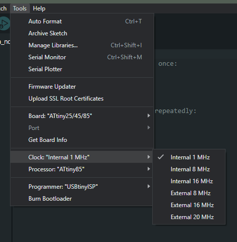
Setting the clock speed for the ATtiny 85 in the Arduino IDE to Internal 1 MHz was needed in my case for the code to work correctly on the chip.
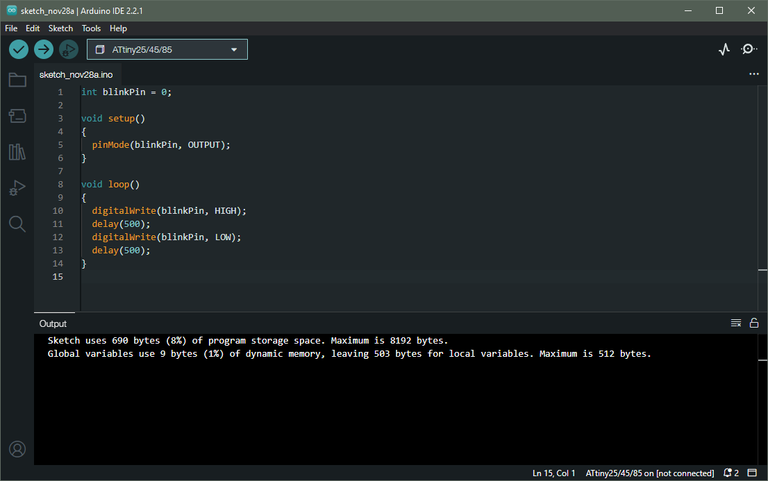
Uploading my first sketch to the ATtiny 85 to test that everything is proceeding as planned.
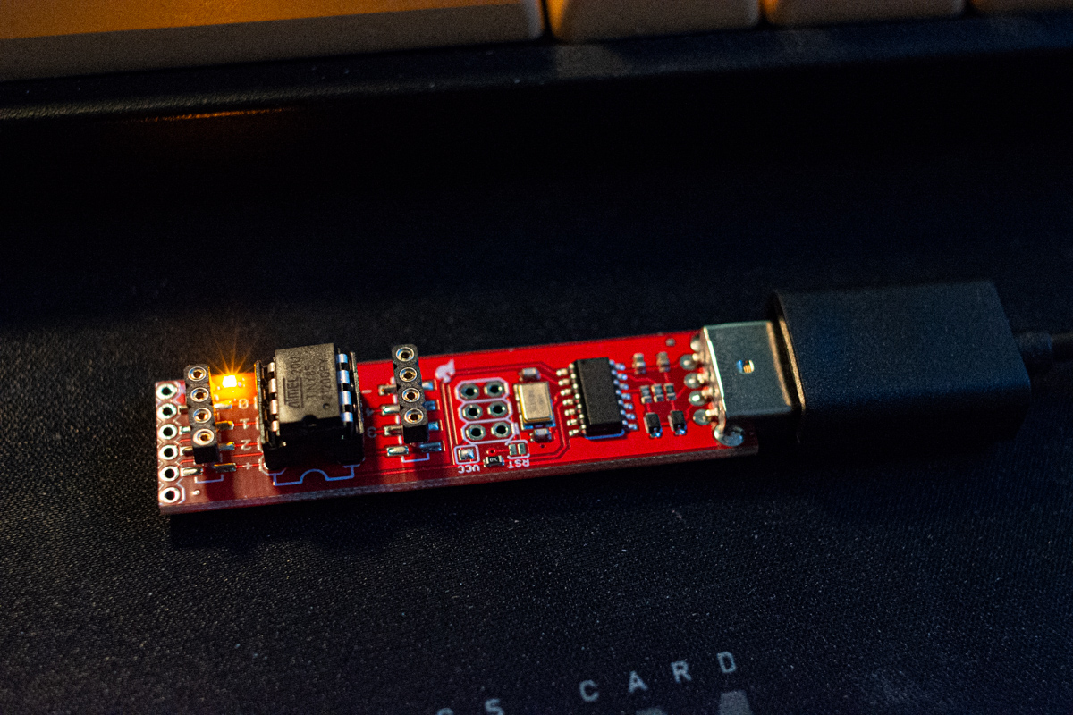
The LED on the programmer board is blinking, being driven by Pin 0 of the ATtiny 85, proving that I can actually program my microcontroller.
The next step was to actually upload Brian’s sketch that plays the Zelda melody to my ATtiny.
|
|
After having sorted out all of the complications in my previous test, this worked flawlessly. Since Brian’s sketch also uses Port 0, I could actually tell by the blinking that commenced on the programmer board’s LED that I’d done something that looked like it was working.
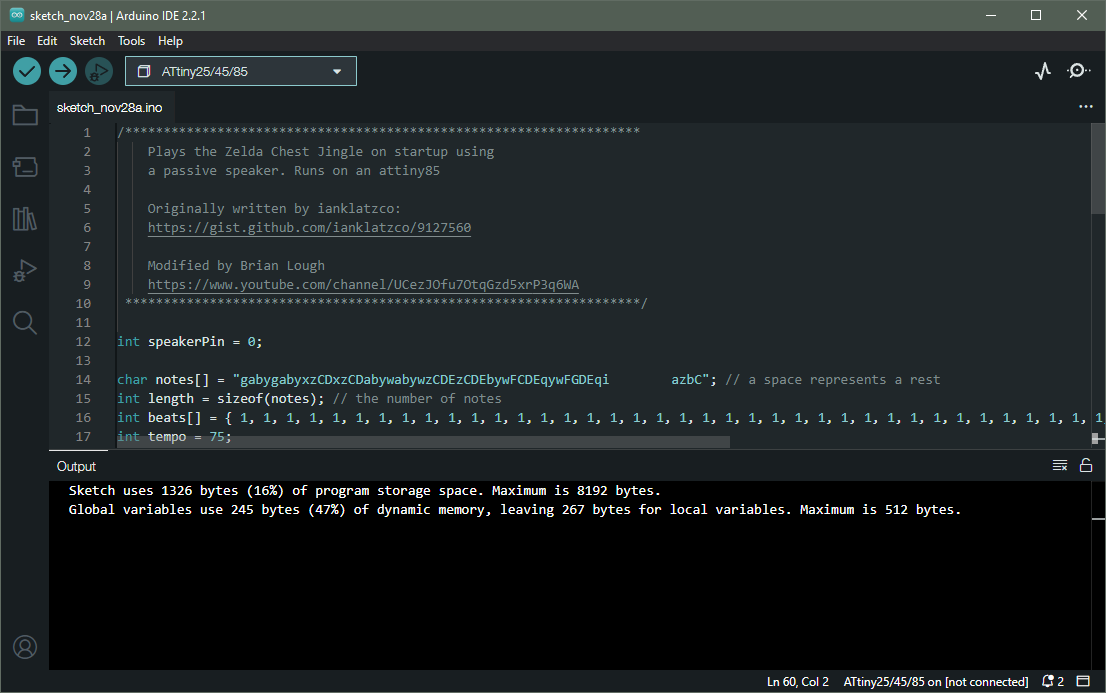
Uploading the sketch I actually want to use for the project. It seems we're using about half of that tiny chip's memory here.
Prototyping the Circuitry
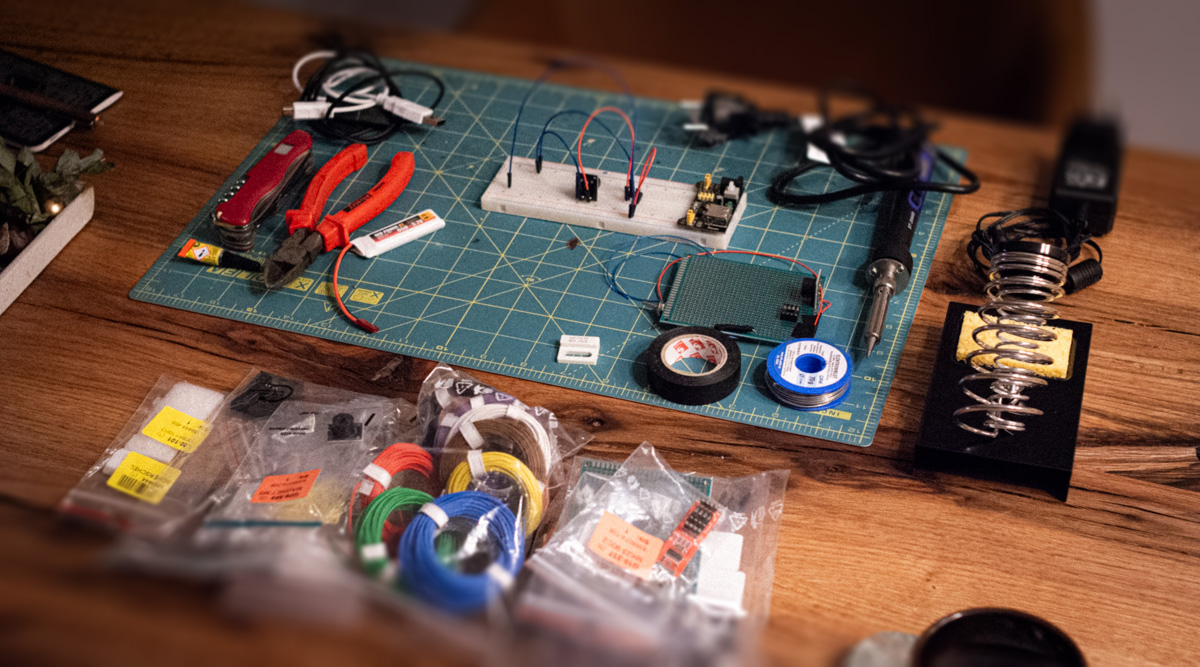
At this point, I was ready to start building my circuit. Since the only thing I’d ever soldered before were a few potis and resistors on my electric guitar, almost two decades ago, I thought it a good idea to prototype the circuit I was going to build. For this, I bought a breadboard, some jumper cables and a breadboard power supply. Since I didn’t need the LEDs from Brian’s project, my circuit would be even simpler than his. For my first test, I also ignored the reed switch and the on/off switch. My initial goal was to see if I’d programmed the ATtiny 85 correctly and could wire it up as well. After some trial and error, which included learning how a breadboard works, I figured it out.
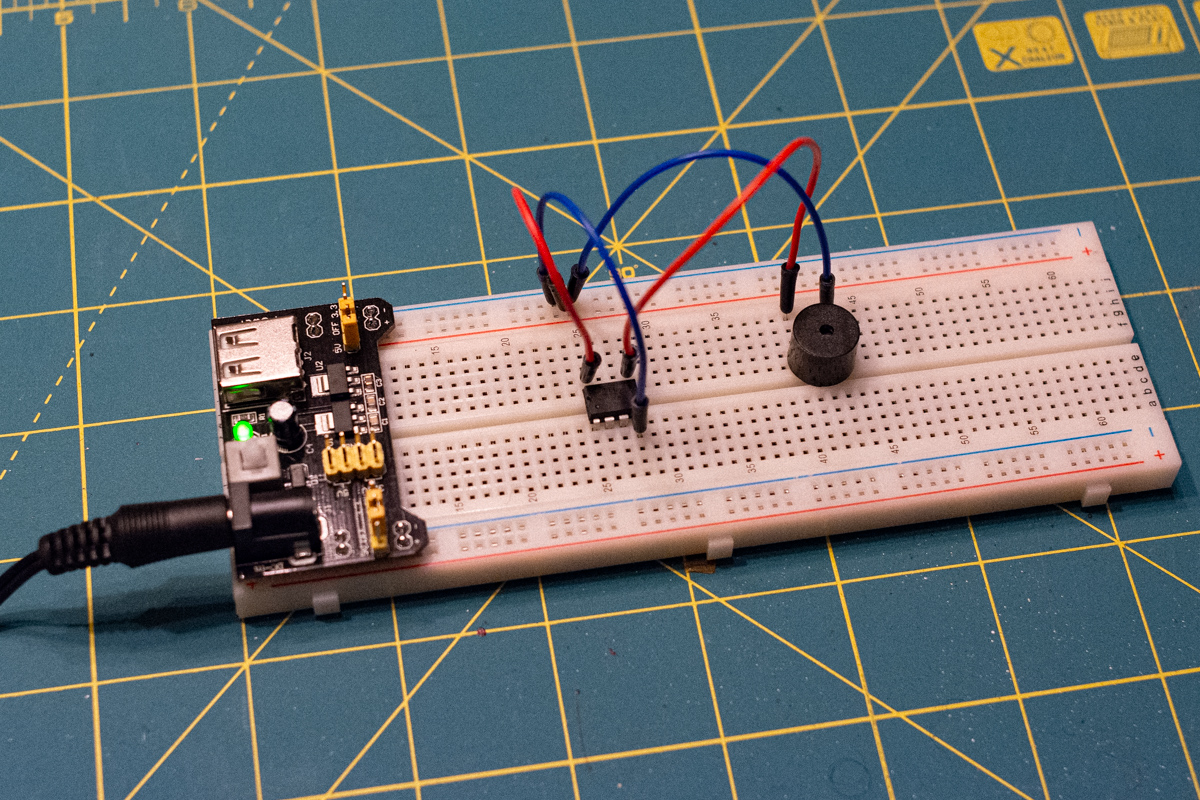
The first circuit I ever built from scratch: An ATtiny 85 powering a passive speaker that plays the Zelda chest opening melody.
In this first circuit, the positive terminal from the power supply is wired to the VCC port of the ATtiny and the ATtiny’s Port 0 is wired to the positive terminal on the passive speaker (red cables). The power supply’s ground terminal is wired to the ATtiny’s GND port and the speaker’s negative terminal (blue cables). When powered on, this simple circuit plays the Zelda jingle once. To play the music again, it needs to be powered off and on again.
I actually think there is an error in Brian’s schematics, as I had to wire the ground connection on the ATtiny 85 to a different pin than him. For reference, here’s the ATtiny 85 pinout diagram from Atmel’s datasheet:
ATtiny 85 pinout diagram (Source: Atmel)
I have VCC wired to the positive terminal of my power supply, PB0 is wired to the positive terminal on my speaker and GND is wired to the negative terminal of the power supply. Brian has PB5 instead of GND wired to ground, if I read his schematics correctly.
With this first test circuit working, it was time to make it more complicated and plug in the reed switch that turns the whole contraption on once a magnet is removed. For this, I wired both the ground terminals on the ATtiny and my speaker to one end of the reed switch. I then had to figure out which of the two contacts on the other side is used in a normally closed (NC) configuration — see Brian’s explanation in his project post, linked above, for more details. What we want is for the whole circuit to be unpowered (the connection to ground broken) while a magnet is near the switch.
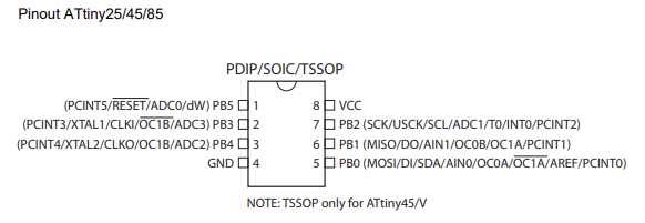
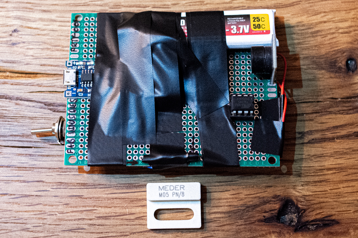
The second iteration of my prototype circuit uses a reed switch in the NC configuration to break the circuit as long as a magnet (the rightmost, white element in the picture) is close by. When that magnet is removed, the circuit is closed and the melody plays, as before.
Note that I swapped out the passive speaker module in this build. The one used in the first iteration of my prototype circuit had a voltage requirement that was slightly too high for my project.
After a few tests, I was satisfied that this configuration works as intended: Nothing happens when I switch on the power, but as soon as the magnet is removed, the Zelda chest melody plays. After putting the magnet back in place, it resets the ATtiny by cutting its power and by removing the magnet again, the music will play once more.
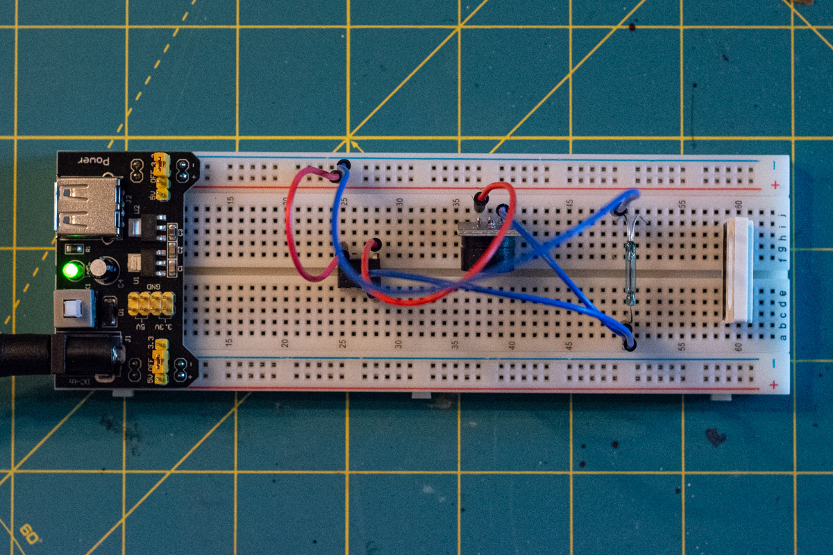
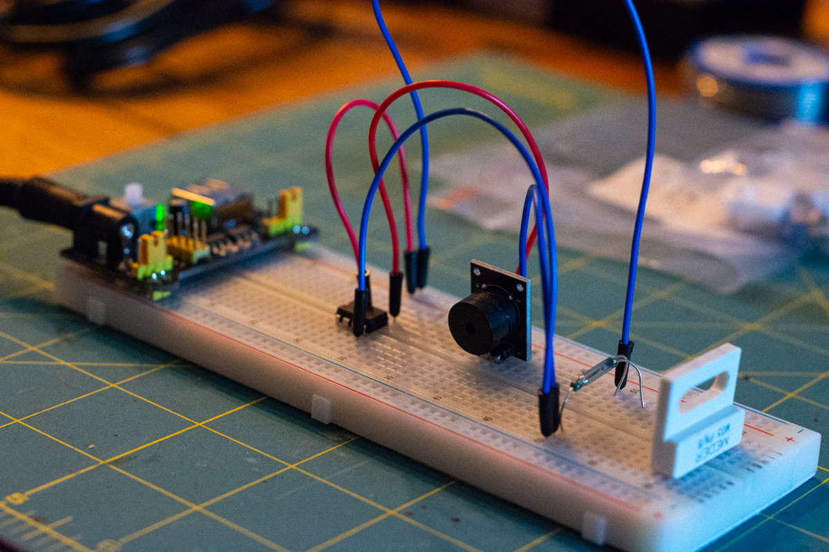
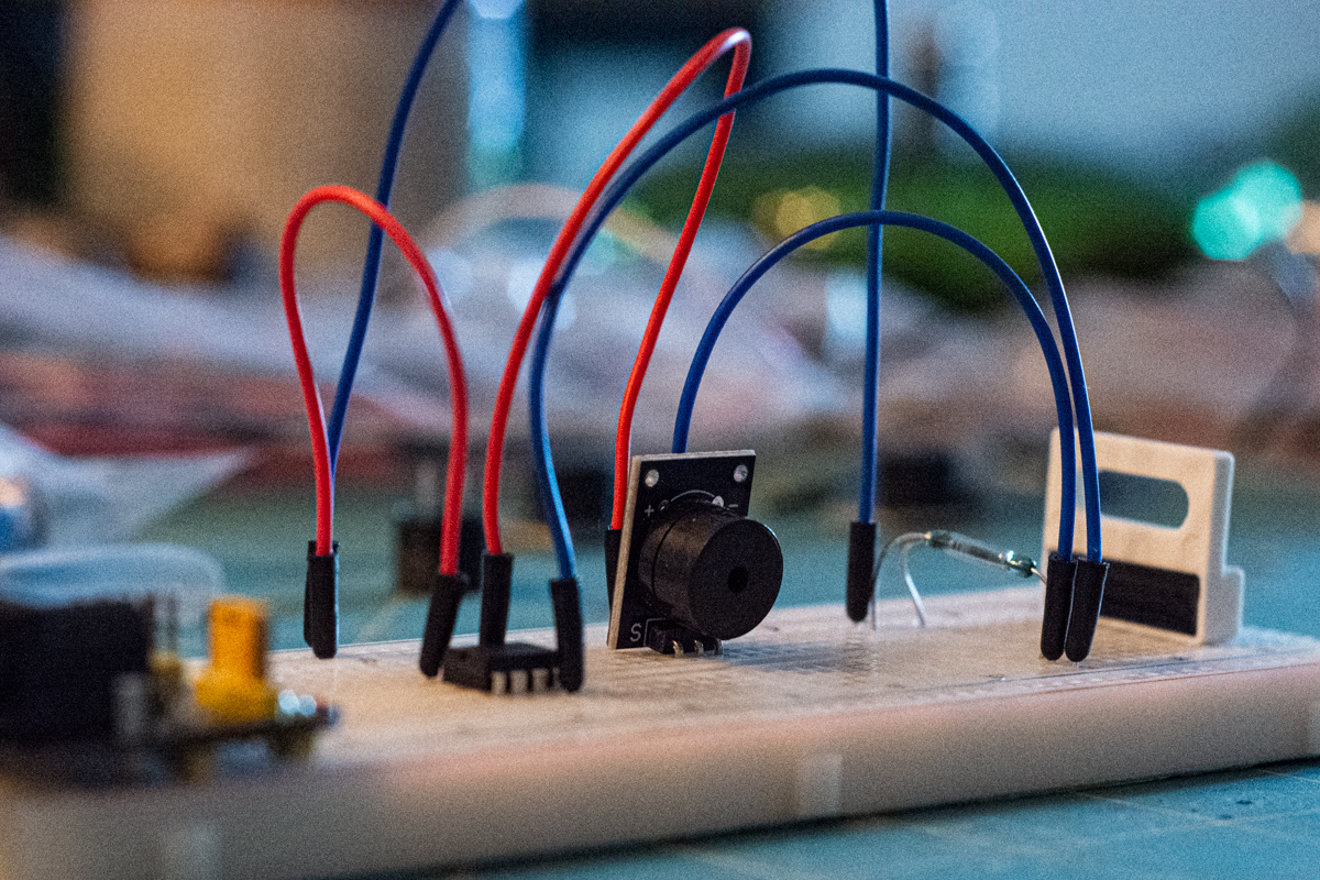
The completed circuit prototyped on a breadboard, working as intended.
Once I’d figured it all out, I was quite amazed to realise how simple this circuit really is. When I permanently solder it to a circuit board in the next step, I will add a lithium polymer (LiPo) battery to power the circuit. The battery will be connected to the circuit via a USB charging unit that can power the circuit directly when it is plugged in. I also plan to wire a simple on/off switch in series behind the reed switch, which allows us to manually turn the whole thing off if we want. This is also a safety feature, since we’re wiring the battery directly into the circuit. As an additional safety precaution, the USB charging unit that controls the power flow to the battery, and from the battery to the circuit, has on-board logic that will make sure that the battery isn’t charged too quickly, overcharged or emptied too much — since all of these things are dangerous when you’re dealing with LiPo technology.
Soldering Everything Together
With the electronics for my project successfully tested, it was time for the exciting part: actually assembling everything on a circuit board permanently. And, believe me, this was quite exciting indeed, as far as I was concerned…
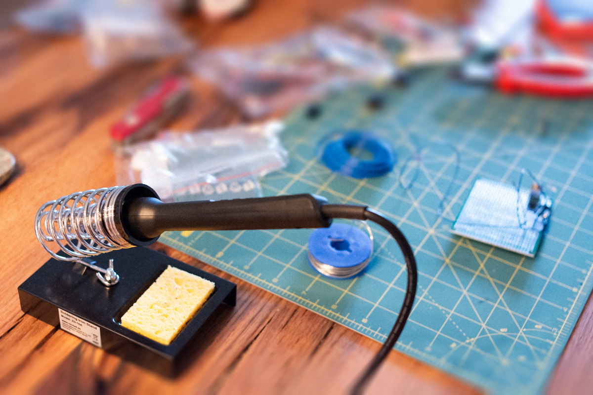
Let's get soldering!
Since I haven’t soldered anything in about twenty years, and even then only once before, I am aware that some of what follows isn’t the most optimally executed wiring work you’ll ever see. But we all start somewhere. And in the end, the whole thing did work, so it’s good enough for now.
My very first solder point on this project was the first time I'd used a soldering iron in about twenty years.
None of these solder points are perfect, but they are good enough. And I'm quite happy with how this board turned out in the end, especially considering my extremely limited experience with doing work like this.
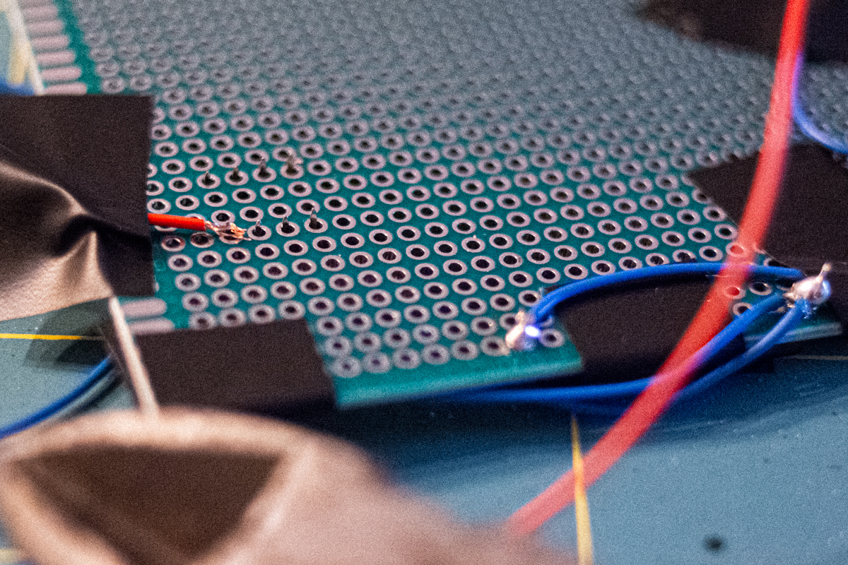
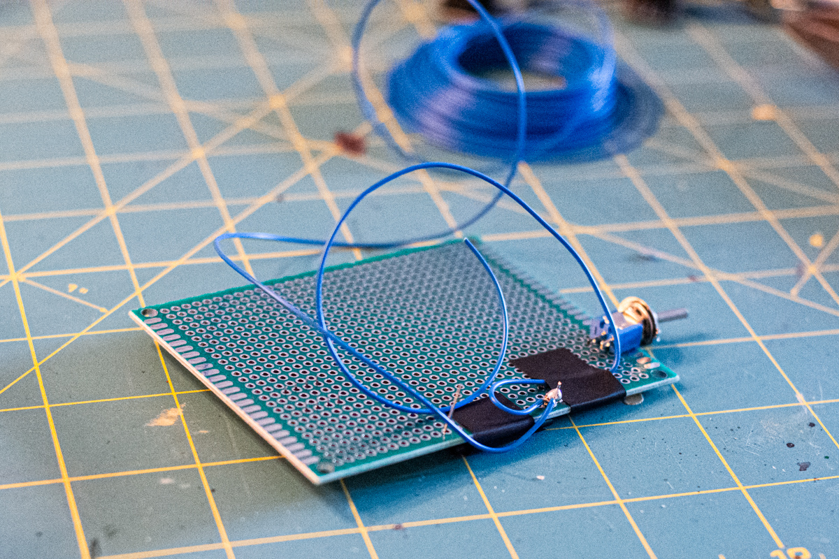
When you try to find out how to solder electronics on the internet, you can find hundreds of guides. Not one of the dozens I read showed how to connect wires to the pins of elements on the underside of the PCB. So I did what I could, based on some text descriptions I'd seen. Shown here: Connecting cables to the pins on the underside of the IC socket, which we'll plug the ATtiny in later, was by far the hardest.
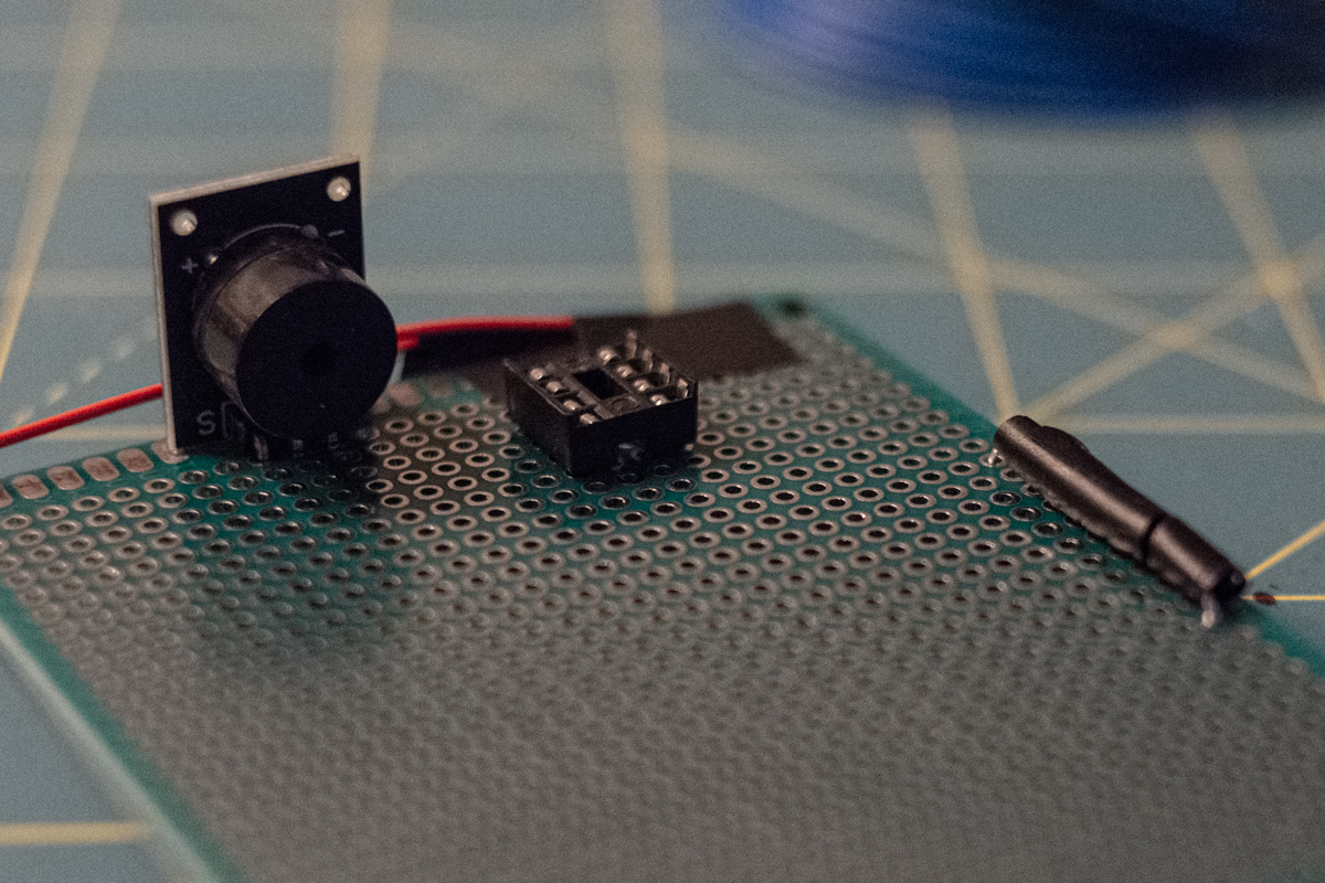
On the top of the PCB, there's only the speaker, the socket for the ATtiny 85 and the reed switch (wrapped in insulation tape to protect the glass housing).
I bought a relatively sturdy circuit board with a simple hole layout and stuck the pins of the components through the holes, before fixing them in place on the backside with some insulation tape. Then I soldered the pins straight to the board and cut them short with a wire cutter. If they had to have wires attached, I stripped the end of the wire and wound the copper around the pin as best as I could before soldering everything in place. Throghout this step, I kept my prototype circuit on the breadboard next to me as a reference and simply repeated that same circuit on the actual PCB.
I used simple stranded wire that I bought in a big pack of different colours, even though with such a simple circuit, I only used red (for the live wiring) and blue (for ground connections). To complete the circuit, I simply soldered one component after the other carefully, until everything was done. Doing it calmly, one step after the other, looking at the breadboard when needed, took much of the considerable anxiety out of the process that I had felt going into it.
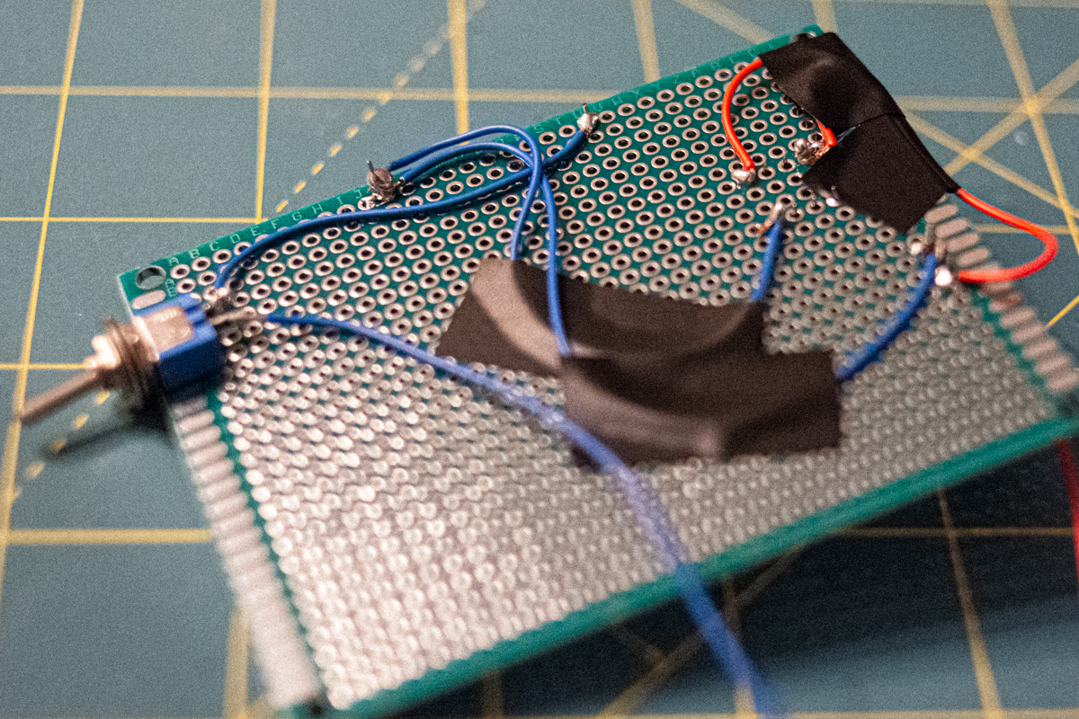
Since the on/off switch I added wasn’t of a through-hole (THT) design, I simply glued it to the side of the board with superglue. I also glued the speaker module onto the board to give it more stability, as it sticks out at a 90° angle. To finish off, I tidied up some of the longer wires by sticking them to the board with insulation tape. I had deliberately picked a board that’s quite roomy to make things easier for me by giving me more room to work with. This came in handy and will also allow for some space to attach the battery in the next step.
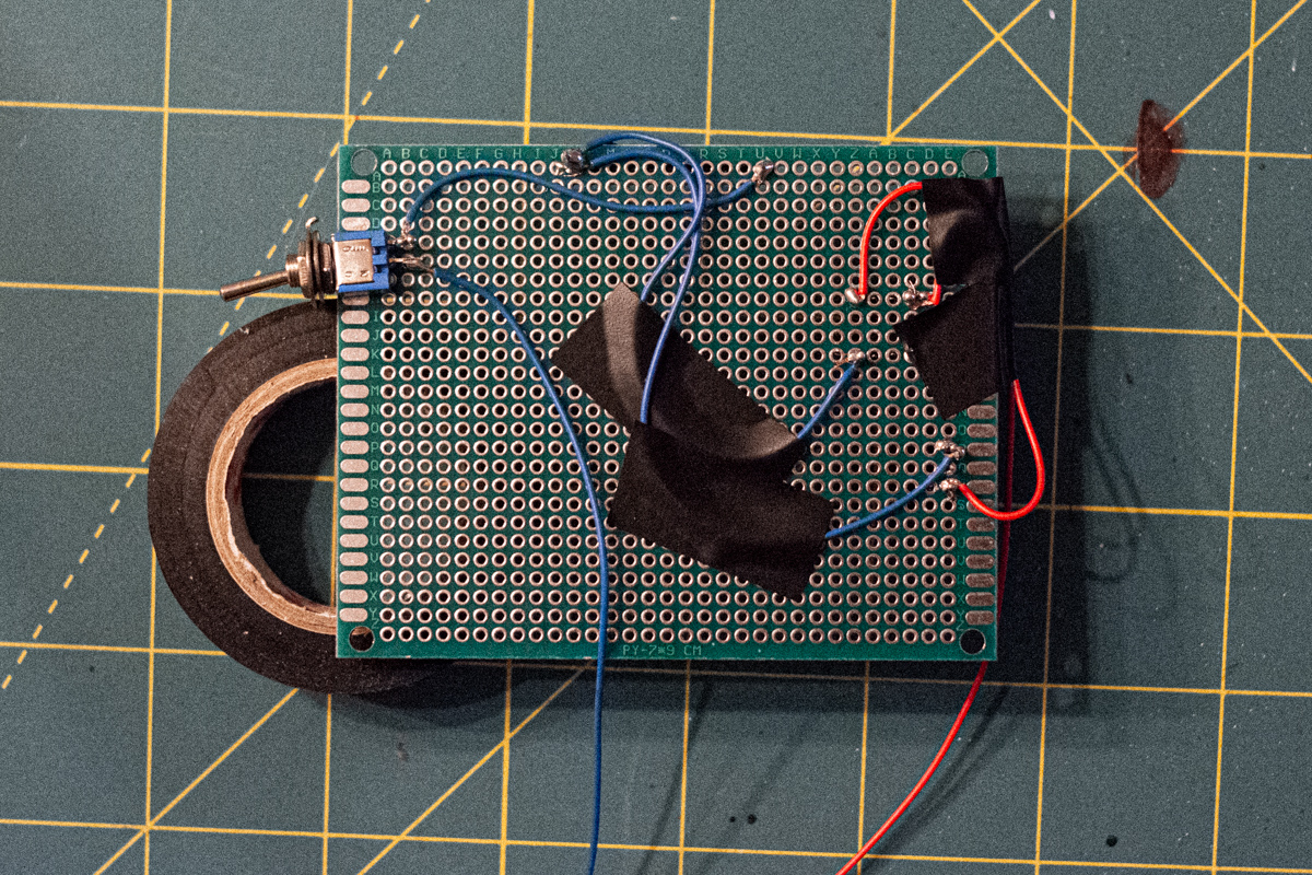
Finished wiring on the backside of my circuit board. Note the toggle switch, which is a new addition to the circuit we prototyped on the breadboard and allows us to switch the whole thing off, even if the reed switch is closed by removing the magnet.
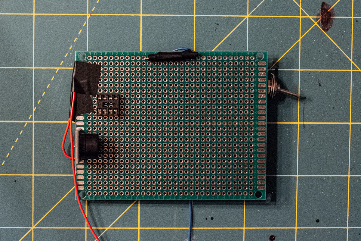
Front side of the finished board. I will plug the ATtiny into the currently empty IC socket once I've wired in the battery and charging unit.
Here Comes the Power!
The main wiring is all done at this point. Now, we have to connect the battery to the USB charging unit and then we can connect that to our finished circuit board and it should all work. Hopefully.
I first glued the charging unit to the main board with superglue to have some stability, as it is quite tiny. Then I glued the ground and live wires from my circuit to the Out - and Out + terminals on the charging unit’s board. I then covered the solder points carefully with insulation tape to protect the circuit from shorts while I soldered in the battery.
Next, I carefully cut the connector off the battery wires. I carefully cut one wire, insulated the bare end thoroughly and then repeated the step with the other wire, taking much care not to have these wires ever touch anything.
Then, I carefully soldered the battery wires to the charging unit, taking care to have the wire only touch the part of the circuit where I wanted to solder it. Here, again, insulation tape is your friend and works well to fix wires in place while you solder. I first soldered in the battery’s live wire (red) to the charging unit’s B+ terminal. I then carefully insulated the solder point. Next, I soldered the battery’s neutral wire (black) to the charging unit’s B- terminal.
The device was now completed and i removed the insulation tape from the charging unit to test the whole thing. It turns out that everything was working as expected. On my first try! I’m pretty proud of that!
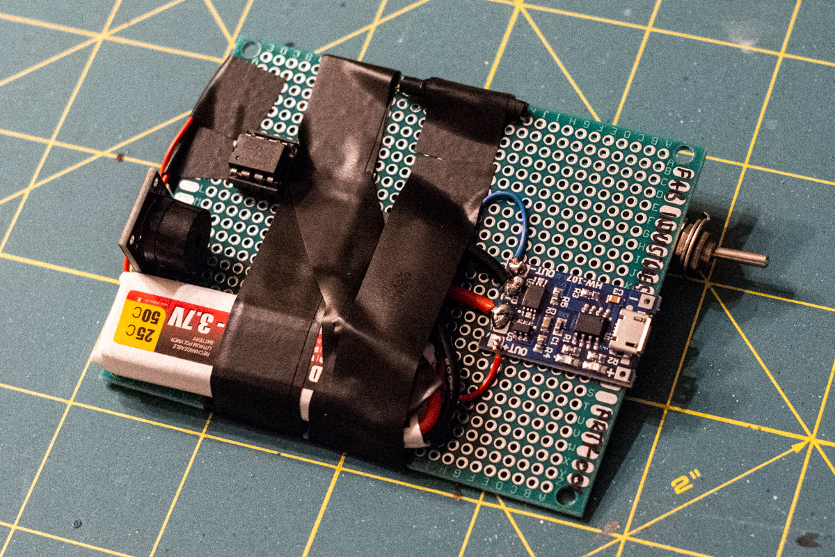
The front of the board with the USB charger wired in and the LiPo battery installed. The solder points are pretty messy, but this was the best I could manage with my extremely limited soldering experience.
After testing everything thoroughly, I carefully covered the solder points on the charging terminal with tape again to prevent shorts from conductive dirt or whatever the device would come into contact with while in use. I then taped the battery to the board with more insulation tape. I didn’t glue it in because it might have to get replaced at some point.
I also covered the wiring and other sensitive parts liberally with insulation tape just to make the whole assembly more robust.
The finished product — liberally protected with insulation tape for good measure.
I am quite amazed with myself that I got this thing working at the first attempt, especially considering that my previous experience with pretty much any of this was non-existent. The breadboard definitely came in handy as I probably would have messed up the circuit (and would have used the wrong kind of speaker) if I hadn’t been able to prototype the circuit first. Some of the soldering also isn’t as pretty as I would like it to be but, hey, it does work and that is all that counts. Here’s the proof:
Granted, the finished product looks a bit like an IED, but my friend seemed pretty happy when I gave her this as her birthday gift and I can’t wait to see — or rather: hear — it in action when she installs it in her beautiful antique wooden storage chest.
It took me about two whole days to research and build, but that time was spread over two to three months in reality. The parts are pretty cheap, but I bought multiples of almost everything, which came in handy when I broke the glass housing of a reed switch simply by handling it. I also bought a new soldering iron with temperature control, since that’s definitely recommended when soldering electronics.
All in all, this was a great first hardware hacking project. Even though it seemed daunting at times, in the end, it was very manageable. And I already have a few ideas of what to build next with the ATtinys and other hardware I have left over.
Components Used in This Project
Here is a list of everything you will need to build this project yourself:
Hardware
- ATtiny 85-20 PU
- 8 pin IC socket (for the ATtiny 85)
- SparkFun Tiny AVR Programmer
- Breadboard, jumper wires, breadboard PSU
- 12 V wall socket power supply (for breadboard PSU)
- Double-sided epoxy circuit board (9 x 7 cm)
- Stranded copper wire for electronics applications
- Dual-mode reed switch
- Simple on/off switch
- Passive speaker module (also called a passive buzzer)
- TC4056 USB charger for LiPo battery with pinout to circuit
- One 3.7 V LiPo battery (at least 500mAh)
Software
- Arduino IDE
- ATtiny plug-in for the Arduino IDE
- Arduino sketch that plays Zelda chest sounds on startup
Tools
- Soldering iron
- Rosin core solder
- Insulation tape
- Superglue
- Wire cutter
- Swiss Army knife (to cut and strip wires)